Illustrative diagram library
Matched reference diagrams for each documented loop
When you generate a document, Loopdraft docks a matched illustrative diagram beside it. Every diagram is a schematic reference — clearly marked illustrative and not for construction — to confirm structure before a competent engineer produces the certified drawing.
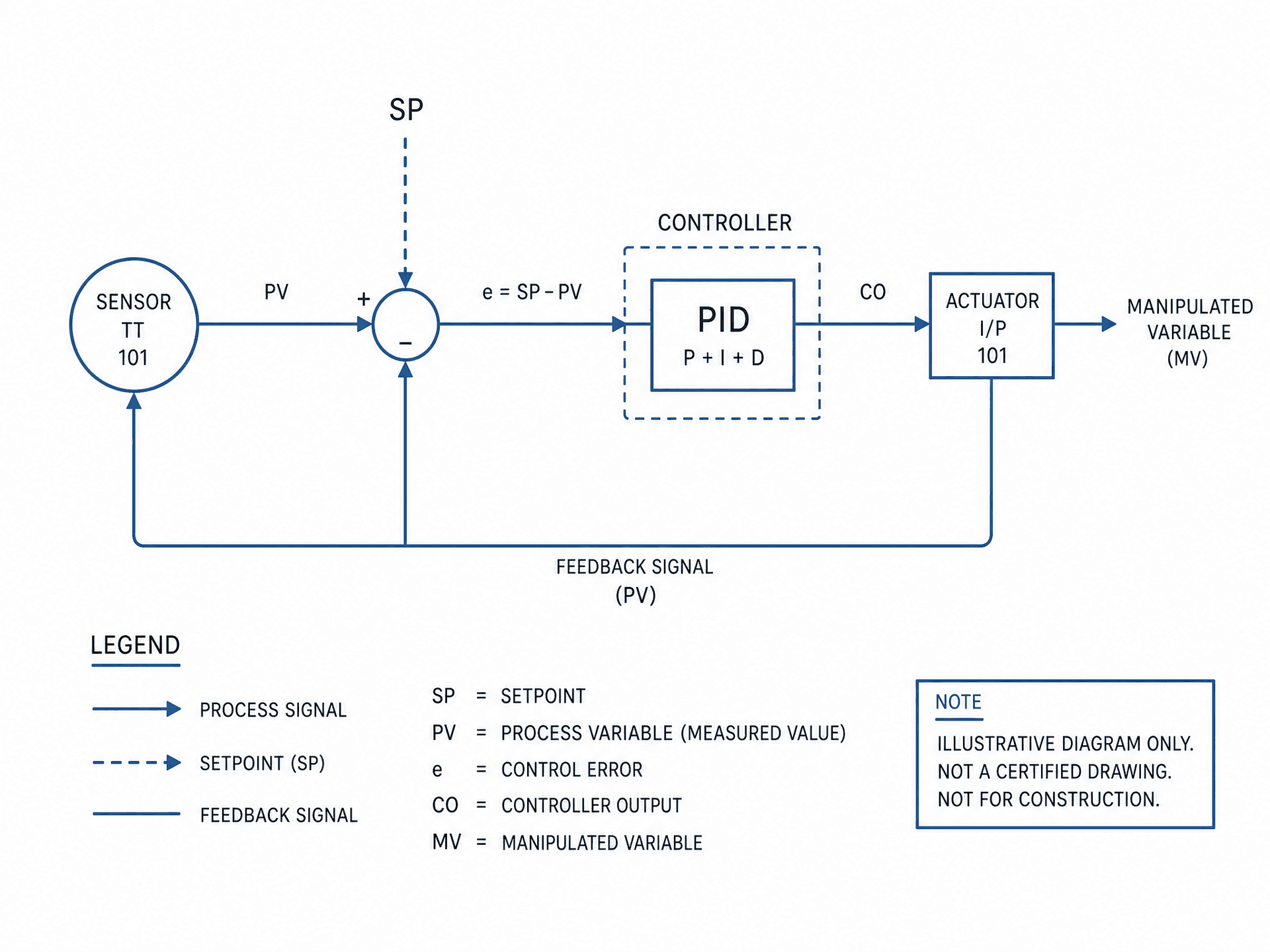
Control loop diagram
Sensor → controller → actuator with setpoint, PID block and feedback path, plus a symbol legend.
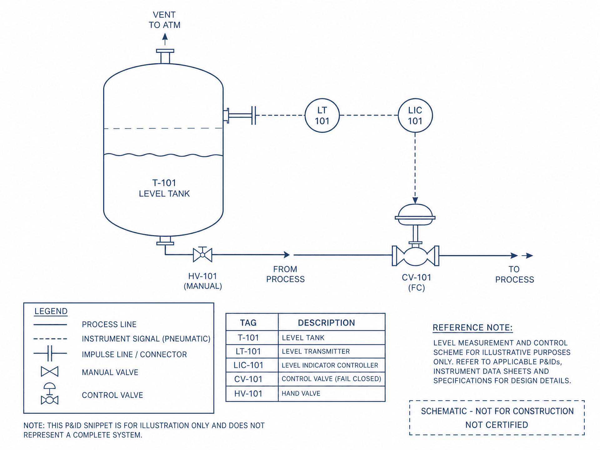
P&ID snippet
ISA-style process and instrumentation fragment: vessel, transmitter, indicating controller and control valve.
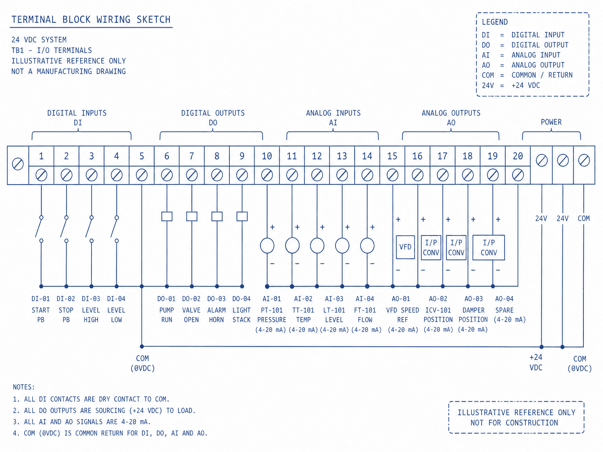
I/O terminal wiring sketch
Terminal block layout grouping DI/DO/AI/AO points with tags, signal types and 4–20 mA notes.
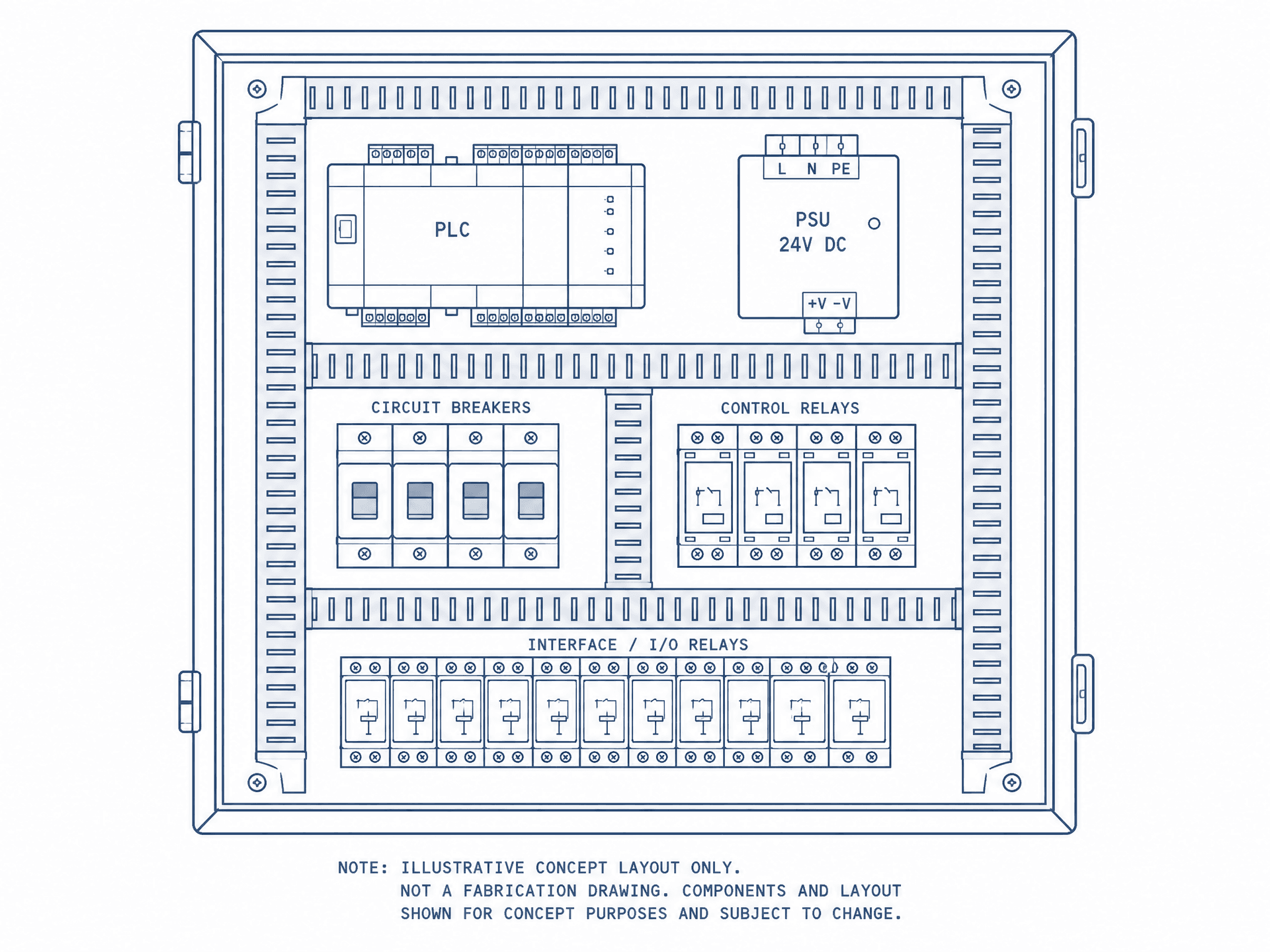
Control panel general arrangement
Concept enclosure layout placing PLC, 24 VDC PSU, breakers, control relays and interface I/O relays.
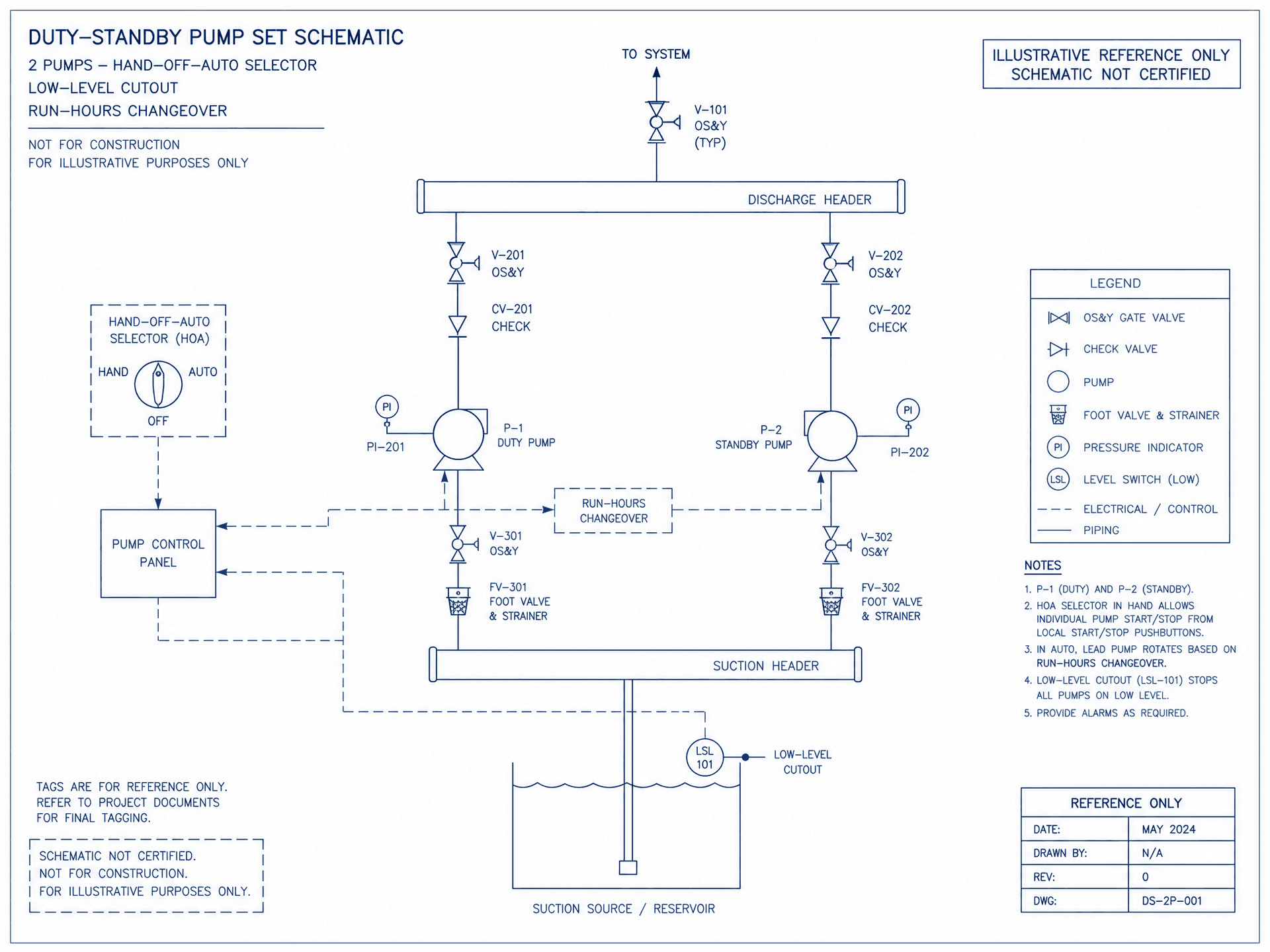
Duty / standby pump schematic
Two-pump set with hand-off-auto selector, low-level cutout and run-hours changeover, with legend and title block.
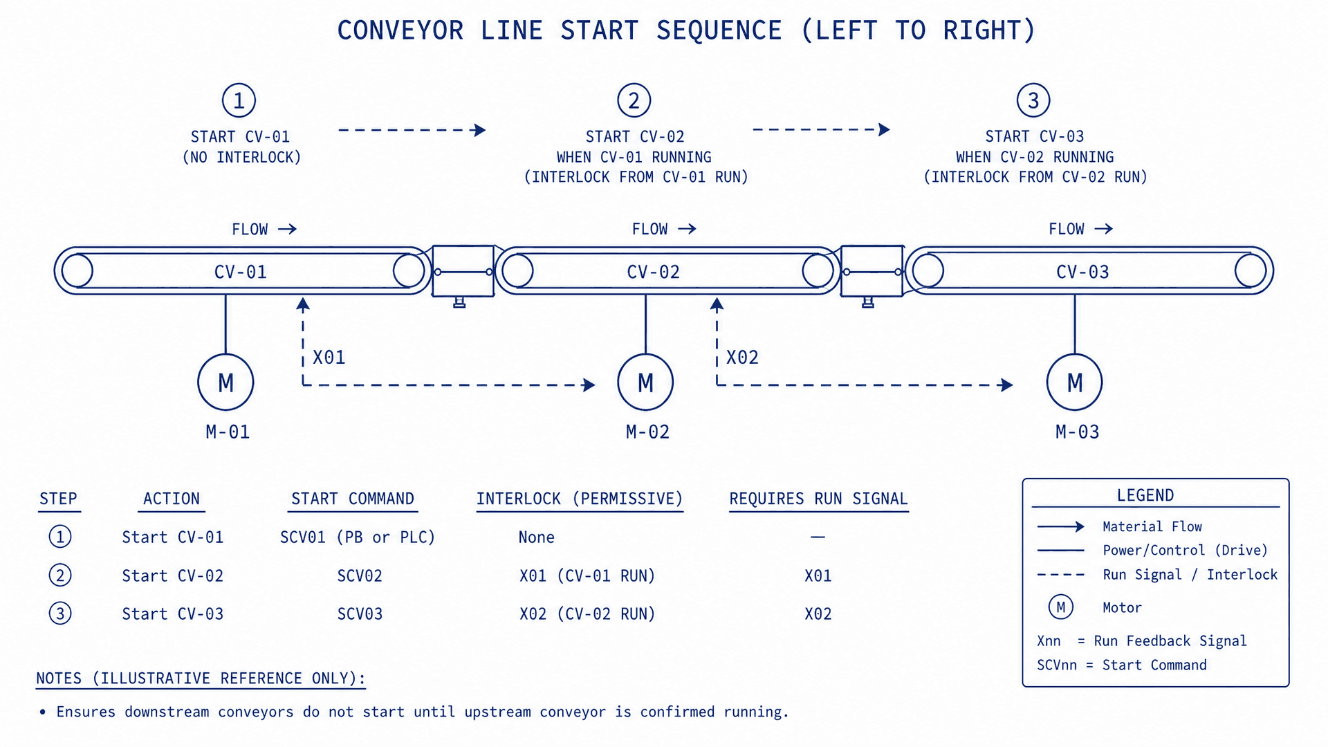
Conveyor start sequence
Three conveyor segments with motors, run-signal interlocks and a step table for cascade start.